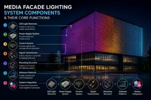
High-rise LED media facades combine long DC runs, high switching currents, exposed metalwork, sensitive electronics, and difficult maintenance access. The electrical design must control voltage drop, transient stress, fault energy, lightning current paths, and safe commissioning from the service entrance to the last pixel.
Key Takeaways
- Distribute AC to local power supplies and keep low-voltage DC branches short, balanced, fused, and accessible.
- Calculate voltage drop from measured resistance, not nominal cable length alone: P = VI and Delta V = I x R.
- Coordinate the lightning protection system, bonding network, SPDs, overcurrent devices, and equipment withstand rating as one system.
- Control inrush and peak load with staged startup, branch separation, thermal derating, and documented protection settings.
- Commission only after isolation, insulation, earth continuity, polarity, SPD status, and functional tests are recorded.
1. Design Basis and Load Study
Collect the fixture voltage, maximum and typical power, power factor, startup behavior, ambient temperature, installation altitude, cable route, enclosure rating, and required brightness scenes. Separate normal operating load from commissioning load and worst-case simultaneous startup. Size feeders, distribution boards, power supplies, conductors, breakers, fuses, contactors, and cooling for the actual duty cycle.
2. Distributed DC Power Topology
A robust high-rise arrangement distributes protected AC to local power-supply cabinets on each facade zone or floor. Each cabinet converts AC to the fixture DC voltage and feeds short, independently protected branches. This topology reduces high-current DC distance, limits fault energy, simplifies isolation, and makes maintenance practical.
Service entrance -> Main switchboard -> Coordinated SPD -> Floor or zone panel -> AC feeder -> Local PSU cabinet -> DC fuse distribution -> LED branches
Keep branch lengths and connector counts consistent. Use separate routes for power and data where required, maintain segregation from lightning down conductors, label both ends of every circuit, and reserve capacity for thermal and future-load margins.
3. Power and Voltage-Drop Calculations
Use the electrical relationships P = V I and Delta V = I x R. For a two-conductor DC circuit, calculate loop resistance from the outgoing and return conductors, including connectors, fuses, terminals, and temperature effects. Then calculate branch current from actual load power and nominal voltage. Long thin runs are the worst case: on linear facade runs the load is distributed along the profile rather than concentrated at one end, so the voltage profile is a slope, not a step.
| Item | Example | Engineering action |
|---|---|---|
| Load power | 480 W at 24 V DC | I = P/V = 20 A |
| Loop resistance | 0.08 ohm including connections | Delta V = I x R = 1.6 V |
| Receiving voltage | 24 V – 1.6 V | Verify fixture minimum operating voltage |
| Loss | P loss = I x Delta V | Review heat and efficiency |
If the calculated drop exceeds the fixture tolerance, shorten the branch, increase conductor cross-section, raise the distribution voltage where the equipment permits, split the load, or move the power supply closer to the load. Recalculate at the maximum design temperature because copper resistance rises with temperature.
4. Inrush, Peak Current, and Derating
Switch-mode power supplies and LED drivers can draw a short inrush current that is much higher than steady-state current. Review the manufacturer inrush waveform, duration, repetition rate, breaker curve, fuse I-squared-t rating, contactor capacity, and generator or UPS limits.
- Use staged startup or programmable delays so all cabinets do not energize simultaneously.
- Apply branch diversity only when it is supported by measured operating data.
- Derate conductors, terminals, breakers, PSUs, and enclosures for ambient temperature, grouping, altitude, harmonic current, and continuous duty.
- Keep normal operating current below the selected protection and supply limits; never use a breaker as a substitute for a load study.
- Test the worst-case scene and the restart condition after a power interruption.
5. Lightning Protection and Surge Coordination
Design the external and internal lightning protection system in accordance with the project risk assessment and the applicable edition of IEC 62305. Bond the facade support structure, cabinets, cable trays, and exposed conductive parts to the equipotential bonding network using a deliberate, low-impedance path. Do not route sensitive LED data or DC conductors beside a down conductor without the required separation or a designed bonding arrangement.
At the service entrance, a Type 1 or Type 1+2 SPD may be required where partial or direct lightning current can enter the installation or where the lightning protection system creates that exposure. At downstream distribution boards, use coordinated Type 2 SPDs for induced and residual overvoltage. A Type 3 device may be used close to sensitive equipment when the coordination study and manufacturer instructions support it. Select voltage protection level, nominal discharge current, maximum discharge current, temporary overvoltage withstand, backup protection, short-circuit rating, and end-of-life indication as a coordinated set.
6. Layered Protection Parameter Table
| Layer | Typical device or control | Parameters to verify | Purpose |
|---|---|---|---|
| Service entrance | Type 1 or Type 1+2 SPD | Iimp or Imax, Up, Uc, backup fuse, short-circuit rating | Divert lightning current or high-energy surge at the origin |
| Zone distribution | Type 2 SPD | In, Imax, Up, Uc, coordination distance | Limit residual and induced overvoltage |
| Local PSU cabinet | Type 2 or Type 3 SPD as specified | Protection level, lead length, status contact, replacement access | Protect drivers and control equipment near the load |
| DC branch | Fuse or electronic protection per branch | DC interrupt rating, time-current curve, polarity, touch protection | Limit fault energy and isolate one branch |
| Structure and cable system | Bonding, separation, shield termination | Continuity, conductor size, routing, corrosion resistance | Control dangerous potential differences and induced currents |
Final ratings depend on the site risk assessment, earthing system, utility characteristics, equipment data, and local code. The installer must verify coordination with the SPD manufacturer and the authority having jurisdiction.
7. Commissioning and Insulation-Test Safety
Insulation testing and first energisation are the two points where a facade installation can cause real injury or real damage; everything before them is mechanical. The electrical safety case rests on a permit-to-work, lockout/tagout on every feeding cabinet, calibrated instruments and one competent person who owns the isolation log — treat every circuit as live until it is isolated, proved dead and secured against re-energization.
The staged sequence from first inspection through burn-in, and the record set that proves it, are set out in the media facade installation guide. This section covers only the electrical requirements the designer has to specify.
- Inspect labels, enclosure seals, cable glands, torque marks, polarity, protective earth, bonding, and physical damage.
- Isolate sensitive drivers, controllers, SPDs, and LED modules before insulation resistance testing unless their manufacturers explicitly permit the test voltage and method.
- Test conductor-to-earth and conductor-to-conductor insulation on isolated circuits at the voltage specified by the design and equipment manufacturers. Record test voltage, duration, temperature, circuit identity, and result.
- Discharge tested circuits, reconnect equipment, verify polarity, and perform earth continuity and protective-device checks.
- Energize one branch at a time with current monitoring. Confirm voltage at the source and at the farthest load under normal and peak scenes.
- Verify SPD indicators, alarm contacts, RCD or equivalent protection, emergency isolation, control fallback, thermal behavior, and restart after interruption.
Never megger through connected electronic equipment, never bypass protective devices to force a start, and never work on exposed conductors during a live scene test. Follow the local electrical code and the equipment manufacturer’s instructions when they are more restrictive.
8. Field Acceptance Records
Handover should include single-line diagrams, load schedules, voltage-drop calculations, protection settings, SPD certificates, bonding and earth test results, insulation records, torque records, thermal observations, branch labels, firmware versions, scene files, photographs, and a maintenance access plan.
Frequently Asked Questions
Should every LED branch have its own fuse?
Usually each branch or defined group should have protection matched to the conductor, driver, connector, and DC fault rating. Confirm selectivity and the manufacturer’s maximum fuse size; one large upstream fuse may not safely protect small branch conductors.
Can a Type 2 SPD replace a Type 1 SPD at the main entrance?
Not where the installation can carry partial lightning current or where the risk assessment requires Type 1 capability. The entrance device and downstream devices must be selected and coordinated for the building’s lightning current path and earthing arrangement.
Why does a facade look uneven at full brightness?
Common causes include voltage drop, unequal branch lengths, thermal derating, connector resistance, calibration differences, and an overloaded power supply. Measure source and load voltage while the scene is operating, then inspect the highest-resistance connections.
Is an insulation test always safe for an LED system?
No. Electronic drivers, SPDs, controllers, and modules can be damaged by a megohmmeter. Isolate or disconnect sensitive equipment and use the approved test method and voltage for the installed system.
How often should surge protection be inspected?
Inspect status indicators and bonding during every scheduled electrical inspection, after a known surge or lightning event, and whenever a fault occurs. Replace a device that indicates end of life or fails the manufacturer’s inspection criteria.
Authoritative Standards and References
- IEC 62305: Protection against lightning
- IEC 61643: Low-voltage surge protective devices
- UL 1449: Surge Protective Devices
- NFPA 780: Standard for the Installation of Lightning Protection Systems
Always use the current adopted edition and confirm local requirements with the engineer of record and authority having jurisdiction.
Need a High-Rise Facade Power and Surge Review?
Send the elevation, feeder schedule, fixture voltage, branch lengths, site lightning protection concept, and operating scenes. Our engineering team can review topology, voltage drop, protection coordination, commissioning records, and maintainability.
Request a B2B engineering consultation for a project-specific design review and quotation.
Project enquiry
Send your drawings. Get a specification you can defend.
Elevation DWG, facade area, closest viewing distance and site country — we reply within 48 hours with a fixture matrix, power and DMX topology, and a quotation. No price-only quotes.
5,000+ projects delivered · 40+ countries · ISO 9001 · CE / UL / RoHS