Key Takeaways
- DMX512 is a robust, interoperable field protocol for distributed fixtures; SPI is a short-distance pixel data interface that is usually embedded inside a controller-to-receiver architecture.
- Choose the protocol from cable length, pixel count, refresh target, fault containment, serviceability, and the required control ecosystem rather than from headline channel speed alone.
- A defensible design documents timing, voltage levels, termination, address maps, power injection, and a recovery plan for every link.
1. Protocol roles in a facade system
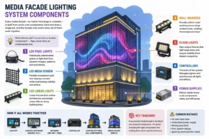
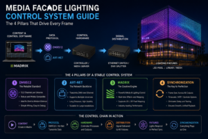
DMX512 and SPI are often compared as if they were interchangeable. They are not. DMX512-A, standardized through ANSI E1.11, is a serial control protocol designed for multidrop links between a controller and lighting receivers. SPI is a synchronous shift-register interface commonly used inside LED pixels, receiver cards, or short controller-to-module connections. A facade may use both: DMX or Art-Net at the building network layer and SPI between a receiver card and addressable pixels. Fixture type constrains this choice as much as topology: linear facade luminaires are normally daisy-chained on DMX512 with one address block per segment, while pixel matrices need SPI at the module level.
Topology and fault containment
A DMX universe carries up to 512 usable data slots after the start code. A typical RS-485 segment should be daisy-chained, terminated at the final device, and isolated from high-energy power conductors. SPI normally uses clock and data conductors, has no universal multidrop standard, and is more sensitive to edge distortion, ground offset, and accumulated propagation delay. Keep SPI runs short unless the selected receiver explicitly specifies differential extension hardware.
2. Timing and engineering calculation
For a DMX frame, the approximate refresh frequency is:
fframe = 1 / [Tbreak + TMAB + (N + 1) x 11 / R]
where N is the number of data slots (1 to 512), R is the baud rate in bit/s, and the factor 11 represents one start bit, eight data bits, and two stop bits. At N = 512 and R = 250,000 bit/s, the slot time is 44 microseconds and the payload time is 22.572 ms. Adding a 1.0 ms break and 12 microsecond mark-after-break gives roughly 23.584 ms, or 42.4 Hz. This is adequate for most architectural fades, but a smaller universe or a split-universe architecture can improve dimming responsiveness.
For an SPI chain, signal flight time is approximately t = L / v, where L is conductor length in metres and v is propagation velocity in metres per second. With L = 8 m and v = 2.0 x 10⁸ m/s, one-way flight time is 40 ns. The larger risk is usually the driver rise time and reflection, not the flight time itself. A 10 ns edge on an unterminated 8 m cable can produce severe ringing; series damping and differential line drivers are safer than simply increasing drive current.
Worked pixel-load example
Assume 1,200 RGB pixels, three 8-bit channels per pixel, and a 30 Hz target. The raw payload is 1,200 x 24 = 28,800 bits per frame. At 800 kbit/s, the transfer time is 36 ms, so one undivided chain cannot meet 30 Hz. Splitting the load into two 600-pixel outputs gives 14.4 ms per output, leaving timing margin for reset and processing. This calculation should appear in the shop drawing, not only in commissioning notes.
3. Parameter comparison
| Parameter | DMX512-A / RS-485 | SPI pixel interface | Design implication |
|---|---|---|---|
| Typical role | Controller to fixture or receiver | Receiver to pixel chain | Use a layered architecture |
| Nominal data rate | 250 kbit/s | Often 400 to 1,200 kbit/s | Verify receiver limits |
| Cable practice | Balanced, shielded, terminated | Short, controlled-impedance, low-noise | Separate from mains |
| Interoperability | High across compliant products | Chip and vendor dependent | Freeze the pixel protocol |
| Fault isolation | Good with splitters and line monitoring | Requires output segmentation | Provide bypass points |
4. Commissioning and documentation
Label every universe, output, pixel direction, power injection point, and spare address. Confirm polarity with a meter before connecting a controller. Test at minimum, nominal, and maximum brightness while logging supply voltage at the farthest pixel. A practical acceptance test includes black-level stability, a full-white thermal run, loss-of-data behavior, and restoration after a controller reboot. For field addressing, the DMX RDM addressing and commissioning guide provides a useful companion workflow.
💡 Engineering Tip
Reserve at least 20% spare capacity in each DMX universe and each SPI output. Spare capacity reduces the temptation to extend an already marginal cable or chain during late-stage changes.
⚠️ Caution
Do not terminate an SPI line with a random 120 ohm resistor. Termination depends on the driver, receiver, and line impedance. Validate the waveform with an oscilloscope at the last receiver under the actual cable and load conditions.
5. Frequently asked questions
Can DMX512 directly drive addressable pixels?
Not usually. A DMX receiver or pixel controller must translate channel values into the pixel IC protocol.
Is SPI always faster?
Its clock can be higher, but total frame rate is limited by pixel count, reset time, processing, and the weakest receiver output. A carefully segmented DMX system can outperform a long unsegmented SPI chain in real projects.
How should a mixed system be tested?
Test the network layer, DMX layer, receiver output, and pixel chain separately, then run an end-to-end pattern. This isolates addressing faults from signal-integrity faults.
References & Standards
- ANSI/ESTA E1.11 DMX512-A official documents
- IEC digital standards and conformity resources
- UL lighting and electrical safety services
- ISO standards catalogue
Need a buildable control architecture?
Share your pixel count, facade zones, cable routes, viewing distance, and target refresh rate with our engineering team. We can prepare a protocol map, load schedule, and commissioning plan for your project.
Project enquiry
Send your drawings. Get a specification you can defend.
Elevation DWG, facade area, closest viewing distance and site country — we reply within 48 hours with a fixture matrix, power and DMX topology, and a quotation. No price-only quotes.
5,000+ projects delivered · 40+ countries · ISO 9001 · CE / UL / RoHS