Executive Summary
- Point-light matrices and linear systems solve different geometric and optical problems.
- Choose by facade curvature, pixel addressability, viewing distance, luminance uniformity, wind exposure, access, and content requirements.
- Use surface coordinates and photometric data to validate coverage before freezing mounting details.
1. Matching the source to the geometry
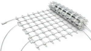
A point-light matrix samples a surface in two dimensions and can follow complex grids, perforated screens, and three-dimensional envelopes. Linear lighting creates a continuous or segmented luminous line and is efficient for reveals, mullions, parapets, and horizontal bands. A hybrid facade frequently uses linear sources for architectural emphasis and point pixels for media content.
Coordinate and spacing model
For a curved surface with local horizontal radius R, chord spacing c, and angular increment alpha, the relationship is c = 2R sin(alpha/2). With R = 12 m and alpha = 2 degrees, c = 2 x 12 x sin(1 degree) = 0.419 m. If the design drawing assumes a 400 mm grid, the difference is 19 mm per interval and will accumulate across the arc. Use developed surface coordinates rather than projecting a flat grid onto a curved elevation.
2. Photometric example
Illuminance from a small source can be screened with E = I cos(theta) / d², where E is illuminance in lux, I is luminous intensity in candela, theta is the angle between the source axis and the surface normal, and d is distance in metres. If a point source provides 1,000 cd toward a surface 8 m away at theta = 30 degrees, E = 1,000 x 0.866 / 64 = 13.5 lux. Real products require the manufacturer photometric file, optical losses, overlap, and surface reflectance to determine the final result.
Uniformity and overlap
For a linear grazing application, check source spacing against mounting distance and beam angle. A narrow optic can create scalloping when fixture spacing is too large; a wide optic can waste flux outside the intended zone. Define target uniformity as Emin/Eavg or Emin/Emax, state the metric, and validate it with a calibrated measurement grid.
3. Parameter comparison
| Parameter | 3D point-light matrix | Linear lighting | Selection question |
|---|---|---|---|
| Geometry | Irregular and doubly curved grids | Edges, reveals, bands | What is the architectural datum? |
| Content | Pixel animation and mapped graphics | Continuous colour and gradients | Is addressability required? |
| Maintenance | More individual nodes | Longer replaceable runs | How is access provided? |
| Wind and structure | Many brackets and cables | Continuous profiles and clips | What is the load path? |
4. Installation engineering
Coordinate brackets with the structural engineer and preserve drainage paths. Avoid creating water traps behind profiles. Define thermal expansion gaps, galvanic isolation, cable bend radius, connector orientation, and replacement access. For point matrices, create a node coordinate file that maps physical locations to media pixels. For linear systems, record cut lengths, end caps, injection points, and maximum run length at the specified colour and brightness.
💡 Engineering Tip
Use a total-station or photogrammetry survey to convert the as-built surface into a coordinate model. A 20 mm survey error can be visually obvious on a tightly controlled media grid.
⚠️ Caution
Do not specify a linear profile by nominal length alone. Confirm maximum continuous run, voltage injection, thermal expansion, photometric distribution, and end-of-run colour consistency.
5. FAQ
Can linear fixtures create media content?
They can create controlled colour patterns and segmented animation, but fine spatial imagery requires a sufficiently dense addressable layout and a controller that matches the segment resolution.
How are curved surfaces tested?
Install a representative mock-up including the actual bracket geometry, surface finish, cable routing, and viewing angles. Measure luminance and uniformity at night and inspect in daylight for glare and visible hardware.
Which system is easier to maintain?
Neither is universally easier. Linear systems reduce node count, while point systems can isolate a single failed node. The access strategy and spare-part plan decide the life-cycle result.
Related engineering guides
- How pixel pitch determines facade resolution
- Transparent LED screen vs LED mesh screen on glass facades
- Architectural linear light installation and thermal detailing
- LED mesh screen specifications and transparency grades
- IP67 vs IP68 for exterior fixture enclosures
- Bridge and coastal facade lighting durability
References & Standards
- CIE photometry and lighting evaluation publications
- IEC standards catalogue
- UL lighting safety resources
- ISO standards catalogue
Planning a complex facade geometry?
Share your surface model, mounting zones, content intent, and target luminance. We can compare point and linear architectures with a coordinate, photometric, and maintenance review.
Project enquiry
Send your drawings. Get a specification you can defend.
Elevation DWG, facade area, closest viewing distance and site country — we reply within 48 hours with a fixture matrix, power and DMX topology, and a quotation. No price-only quotes.
5,000+ projects delivered · 40+ countries · ISO 9001 · CE / UL / RoHS