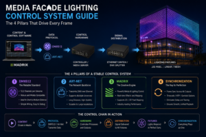
An outdoor LED facade lighting installation is not a collection of lamps — it is a layered control system in which an instruction born in software travels through networks and controllers, gets translated into a precise electrical signal, and finally emerges as a photon from a specific LED at a specific brightness and color. Understanding facade lighting means understanding that signal chain.
This section traces the entire system, component by component, in the order the data actually flows: from the outdoor LED facade lighting solutions software that authors a scene, down through the communication network and controllers, into the DMX or SPI data lines, and finally into the LEDs — all of it kept alive by the power supply layer running quietly underneath.
The System at a Glance: Seven Layers Working as One
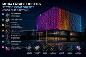
Before tracing the flow, it helps to see the whole. A complete facade system stacks seven functional layers:
- Software — where the light show is designed and scheduled
- Communication — the network carrying instructions across the building
- Controller — the “brain” translating creative intent into fixture commands
- Signal protocol (DMX or SPI) — the language spoken to the fixtures
- Power supply — the energy source feeding both data devices and LEDs
- The LED fixture — driver, LEDs, and optics producing the actual light
- Feedback (increasingly) — fixtures reporting status back up the chain
Each layer only talks to its neighbors. Software never addresses an LED directly; it hands intent to a controller, which speaks a protocol, which drives the fixture. This separation is what makes large, complex facades manageable.
Layer 1 — Software: Where the Light Begins
Authoring the Scene
Everything starts in control software running on a PC or dedicated processor. Here a designer builds scenes: which fixtures light up, in what color, at what brightness, in what sequence, and on what timeline. For media facades, this software maps video or animation content onto the physical grid of pixels — a process called pixel mapping, where each real fixture is assigned a coordinate so the software knows which pixel plays which part of the image.
Scheduling and Automation
Beyond live design, software handles scheduling — sunset-triggered start times via astronomical clock, weekday-versus-weekend scenes, holiday themes, and late-night dimming for energy and light-pollution compliance. Once programmed, the show runs autonomously; no operator needs to be present night after night.
Output: Data, Not Light
Critically, software produces data, not electricity. Its job ends when it hands a stream of instructions — “fixture 240 → red at 80%, fixture 241 → red at 60%…” — to the communication layer for delivery. Everything downstream exists to carry and execute that intent faithfully.
Layer 2 — Communication: Moving Instructions Across the Building
Network Protocols Carry the Load
On any facade larger than a few fixtures, raw lighting data is too voluminous to send over a single cable. Instead, software transmits over Ethernet-based network protocols — most commonly Art-Net and sACN (Streaming ACN / E1.31). These encapsulate lighting data into standard network packets, letting a single Cat6 or fiber line carry hundreds of channels’ worth of instruction across the building at high speed.
Universes: How Data Is Organized
Lighting data is grouped into universes, each universe carrying up to 512 channels (the DMX standard). A large media facade may use dozens or hundreds of universes simultaneously. Network protocols like sACN let all of them travel over one physical network, each tagged with a universe number so the receiving devices know which data is theirs.
Why the Backbone Matters
On tall towers or long bridges, the communication backbone often uses fiber optics for distance and noise immunity, converting to copper only near the fixtures. Underestimating this layer is one of the most common project failures: the fixtures work individually, but signal integrity over long runs collapses, and the facade can’t be reliably addressed as a whole.
Layer 3 — The Controller: Translating Intent Into Commands
The Brain of the System
The controller (often called a processor, master controller, or in pixel systems an “artnet-to-SPI controller”) sits between the network and the fixtures. It receives the high-level network stream and converts it into the specific low-level signal each fixture group understands — DMX for architectural fixtures, SPI for addressable pixel strings.
Distributing to Zones
Large facades are divided into zones, each served by its own controller or output port. The master controller receives the full show over the network, then distributes the relevant slice to each zone’s fixtures. This distributed architecture keeps cable runs short and makes troubleshooting local rather than building-wide.
Standalone vs. Networked Operation
Many controllers can also store scenes internally and run them without a live PC connection — the computer programs the show, uploads it, and disconnects. This standalone capability is essential for permanent installations, where a fixture must run reliably for years without a dedicated operator or a PC left running.
Layer 4 — DMX and SPI: The Two Languages of Fixture Control
The controller must speak the fixture’s native language. In facade lighting, that language is almost always DMX512 or SPI — and the difference between them is fundamental.
DMX512: Addressed, Robust, Long-Distance
DMX512 is the architectural and stage-lighting standard. Each fixture is assigned a start address, and the controller sends a continuous stream of 512 channel values per universe. A fixture “listens” only to the channels at its address — say, channels 100–103 for its red, green, blue, and white levels.
DMX’s strengths are robustness and distance: it runs over shielded twisted-pair cable (RS-485), tolerates electrical noise well, and reaches long runs with repeaters. Its limit is the 512-channel ceiling per universe — an RGB fixture uses 3 channels, so one universe controls only ~170 such fixtures before a new universe is needed.
SPI: For Dense, Addressable Pixels
SPI (Serial Peripheral Interface) drives addressable pixel products — LED strings and nodes where each pixel contains a tiny driver chip (e.g., the WS2811/WS2812, SK6812, or similar) that reads its data and passes the rest down the line. There’s no fixed address; each pixel simply takes the first data packet and forwards the remainder to the next pixel in the chain.
SPI allows enormous pixel counts at fine resolution — ideal for media facades. Its weakness is the mirror of DMX’s strength: SPI signals degrade quickly over distance (typically only a few meters between the controller and the first pixel), demanding controllers physically close to the fixtures, which is exactly why zoned, distributed architecture matters.
Why Both Exist
Neither protocol is “better.” DMX excels at robust control of discrete architectural fixtures over distance; SPI excels at high-density pixel arrays at close range. Many large facades use both — DMX for wall washers and floods, SPI for pixel media zones — with the controller bridging the network to each.
Layer 5 — Power Supply: The Energy Beneath Everything
Two Things Need Power
The power layer feeds two distinct loads: the low-voltage electronics (controllers, signal repeaters) and the LEDs themselves. Most facade fixtures run on low-voltage DC — commonly 24V — converted from mains AC by dedicated power supplies (drivers).
Voltage Drop: The Silent Constraint
Low voltage is safer and standard for linear and pixel products, but it introduces voltage drop: over a long cable run, resistance bleeds off voltage, so pixels far from the supply receive less than those near it — visible as dimming or color shift along a strip. Designers counter this by injecting power at multiple points along a run and keeping runs within calculated limits. Ignoring voltage drop is a classic cause of a facade that fades unevenly toward its edges.
The Driver as Weak Point
Within each fixture, the driver converts and regulates power to the exact constant current the LEDs need. Because heat and electrical stress concentrate here, the driver — not the LED — is statistically the first component to fail. Quality, brand-name drivers with long warranties are the single largest lever on system longevity.
Sizing and Headroom
Power supplies are sized with headroom (typically running at 70–80% of rated capacity) so they don’t run hot and shorten their own life. An undersized or maxed-out supply overheats, and heat is the enemy of every electronic component in the chain.
Layer 6 — The LED Fixture: Where Data Becomes Light
The Final Translation
At the end of the chain, the fixture performs the last conversion: electrical signal into photons. The driver sets the current; the LED converts it to light through electroluminescence; and the optics — lenses and reflectors — shape that light into a defined beam, from a 10° spot to a 120° wash.
Color Mixing
In RGB/RGBW fixtures, separate LED channels (red, green, blue, and often white) are driven at independently controlled levels. By varying the current to each channel — exactly as instructed by the data that traveled the whole chain — the fixture mixes virtually any color, or a clean tunable white in RGBW units.
Consistency Across the Array
For a facade to look uniform, hundreds of fixtures must render the same command as the same color. This depends on tight LED binning (ideally SDCM ≤3, a 3-step MacAdam ellipse) so that “red at 80%” looks identical on fixture 1 and fixture 500 — both at installation and as they age.
Layer 7 — Feedback: The System Talks Back
From One-Way to Two-Way
Traditional DMX is one-way — the controller talks, fixtures only listen. Modern systems increasingly add feedback through protocols like RDM (Remote Device Management), which rides on the same DMX line and lets the controller query fixtures: report your address, your temperature, your fault status.
Why It Matters for Facades
On a facade where fixtures may be 150 meters up a tower, remote diagnosis is transformative. Instead of dispatching rope-access technicians to find a dead fixture, the system reports which fixture failed and often why — turning maintenance from a search into a targeted repair. This closes the loop, making the seven-layer system not just a broadcaster of light but a self-reporting instrument.
The Complete Signal Flow, End to End
Putting it together, a single instruction travels like this:
Software authors “fixture 300 → warm white at 50% at 8:00 PM” → Communication layer wraps it in an sACN packet and sends it over fiber/Ethernet → Controller receives the universe, extracts the data for its zone → converts it to DMX (for a wall washer) or SPI (for a pixel) → the signal reaches the fixture, whose driver — fed by the power supply — sets the precise current → the LEDs emit warm white at 50%, shaped by the optics → RDM feedback confirms the fixture is healthy and on.
All of this happens continuously, dozens of times per second, across thousands of fixtures — which is why the system, not any single component, is what actually “works.”
Comparison Table: DMX vs. SPI in Facade Systems
| Attribute | DMX512 | SPI (Addressable Pixel) |
|---|---|---|
| Addressing | Fixed start address per fixture | No address; data passed pixel-to-pixel |
| Channels / capacity | 512 channels per universe (~170 RGB fixtures) | Thousands of pixels per controller |
| Cable & distance | RS-485, long runs with repeaters | Short runs (a few meters) before signal loss |
| Noise immunity | High (shielded twisted pair) | Lower; sensitive to interference |
| Best for | Architectural fixtures: washers, floods, spots | Dense media facades, pixel animation |
| Feedback | Yes, via RDM | Generally one-way |
| Typical failure mode | Address/universe misconfiguration | Signal degradation over distance |
FAQ
Q: Does the software control the LEDs directly? No. Software produces data and hands it to the communication network. A chain of controllers and protocols translates that intent step by step; the software never touches a fixture directly.
Q: What’s the practical difference between DMX and SPI? DMX is robust over long distances and uses fixed addresses — ideal for discrete architectural fixtures. SPI drives dense addressable pixels at close range for media effects but degrades quickly over distance.
Q: What are Art-Net and sACN? Network protocols that carry lighting data over standard Ethernet, letting one cable transport many DMX universes across a large building — the communication backbone of modern facades.
Q: Why do pixels far from the power supply look dimmer? Voltage drop. Resistance over a long low-voltage run reduces voltage at the far end. Designers inject power at multiple points and limit run lengths to keep brightness even.
Q: Can a facade run without a computer connected? Yes. Most controllers store scenes internally and run them standalone on a schedule — the PC is only needed to program and update the show.
Q: Which component fails first? Statistically the driver, due to concentrated heat and electrical stress — not the LED. This is why driver quality dominates real-world system lifespan.
References
- ANSI E1.11 (USITT DMX512-A) — Entertainment Technology, USITT DMX512-A Asynchronous Serial Digital Data Transmission Standard 🔗 https://tsp.esta.org/tsp/documents/published_docs.php
- ANSI E1.31 (sACN) — Lightweight streaming protocol for transport of DMX512 over ACN 🔗 https://tsp.esta.org/tsp/documents/published_docs.php
- ANSI E1.20 (RDM) — Remote Device Management over DMX512 networks 🔗 https://tsp.esta.org/tsp/documents/published_docs.php
- U.S. Department of Energy, Solid-State Lighting Program — LED driver reliability and system research 🔗 https://www.energy.gov/eere/ssl/solid-state-lighting
- IES LM-79 / LM-80 — Photometric measurement and lumen maintenance standards 🔗 https://store.ies.org/
- ANSI C78.377 — Chromaticity (SDCM/MacAdam ellipse) specification for SSL products 🔗 https://webstore.ansi.org/